VACS:Projects:Hardware:LPS:LcdPanelBoard
| (One intermediate revision by one user not shown) | |||
| Line 16: | Line 16: | ||
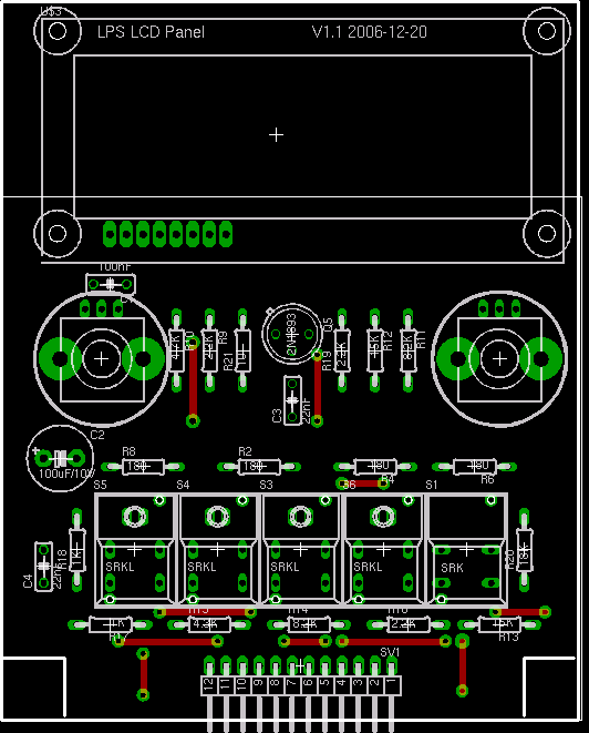
[[Image:lps_lcd_panel_board_placement.png|thumb|512px|left|LCD Panel Placement]] The circuit is made on a 90mm x 111mm PCB using 35um copper. The major constraint concerning the layout is about the final panel interface, in particular there should be enough room arround each wheel so that we can turn them without pressing any other button. The height of the board is defined by the buttons and the LCD display module. | [[Image:lps_lcd_panel_board_placement.png|thumb|512px|left|LCD Panel Placement]] The circuit is made on a 90mm x 111mm PCB using 35um copper. The major constraint concerning the layout is about the final panel interface, in particular there should be enough room arround each wheel so that we can turn them without pressing any other button. The height of the board is defined by the buttons and the LCD display module. | ||
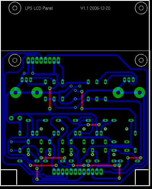
| − | [[Image: | + | [[Image:lps_lcd_panel_board_bottom.png|thumb|512px|left|LCD Panel PCB]] The board layout is made with the following constraints (DRC checks): |
<table border="1"> | <table border="1"> | ||
| Line 42: | Line 42: | ||
<br clear="all"/> | <br clear="all"/> | ||
| + | |||
==Documentation== | ==Documentation== | ||
Below is a collection of datasheets, white papers and articles related to the parts used in the board. | Below is a collection of datasheets, white papers and articles related to the parts used in the board. | ||
===Resistors=== | ===Resistors=== | ||
* {{HardwareDoc|rcl/metal-film-resistor.pdf|Metal Film Resistor}} | * {{HardwareDoc|rcl/metal-film-resistor.pdf|Metal Film Resistor}} | ||
| − | |||
| − | |||
| − | |||
| − | |||
| − | |||
===LCD and Buttons=== | ===LCD and Buttons=== | ||
| Line 58: | Line 54: | ||
===Semiconductors=== | ===Semiconductors=== | ||
| − | |||
| − | |||
* {{HardwareDoc|transistors/2N1893.pdf|2N1893}} | * {{HardwareDoc|transistors/2N1893.pdf|2N1893}} | ||
| − | |||
| − | |||
| − | |||
Latest revision as of 23:36, 15 February 2007
| Status | |
|---|---|
| Schema finished | |
| Validated the schema | |
| Validated the board layout | |
| Board manufactured | |
| Board finished | |
| Board tested | |
Contents |
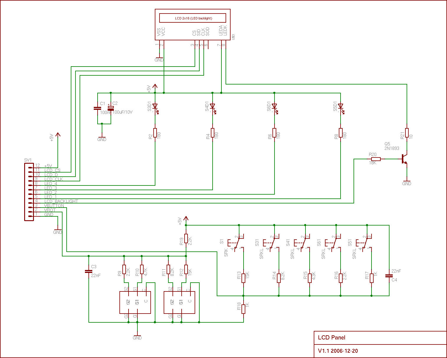
Description
The LCD panel board integrates a 2x16 LCD display, two wheels and five buttons. It is directly connected to the LPS Master Controller which drives the LCD and scans the keyboard and wheels. The button status are read using a single input. Each button are connected to the +5V and to a specific resistor connected all together. A resistor is connected to the ground so that it forms a voltage divisor. The resistors are such that a different voltage is obtained for every possible button combination (32).
The two wheels follow the same scheme. Each wheel contains two internal switches which are ON or OFF depending on the wheel position. The sequence in which the two switches are activated or deactivated determines the direction in which the wheel is turned. Each wheel switch is connected to the ground and has a specific resistor connected all together. A resistor is connected to the +5V so that it forms a divisor. This is similar to the buttons but we have only 16 different combinations.
The LCD module is an SPI serial module (The choice was motivated by the fact that I already had one). The LCD module has a backlight led that is driven by a [2N1893 ] transistor.
Schema
PCB
The circuit is made on a 90mm x 111mm PCB using 35um copper. The major constraint concerning the layout is about the final panel interface, in particular there should be enough room arround each wheel so that we can turn them without pressing any other button. The height of the board is defined by the buttons and the LCD display module. The board layout is made with the following constraints (DRC checks):| Signal class | Width | Clearance | Drill |
|---|---|---|---|
| Supply and GND | 1mm | 0.3mm | 0.8mm |
| signal | 0.8mm | 0.3mm | 0.6mm |
Despite the simplicity of the schema the board routing was not easy to make on a single sided board. This was due to the number of connections that exists for the connector.
Documentation
Below is a collection of datasheets, white papers and articles related to the parts used in the board.
Resistors
LCD and Buttons
- [KS0074 (LCD parallel/serial driver) ]
- [Bourns PEC16 Incremental Encoder ]
- [Digitast Microminiature SPDT, Key Switches ]
Semiconductors
- [2N1893 ]


