Output Current Protection
Output Current Protection
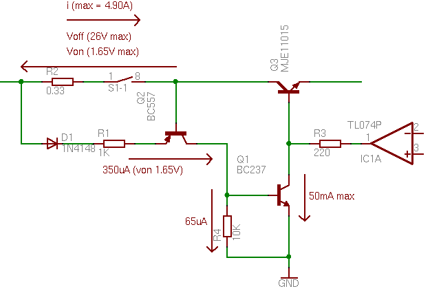
The system has in fact two output current protections. One in the [VACS:Projects:Hardware:LPS:ControllerBoard power supplt controller board] and another one in the voltage regulator board. The first protection has an impact on the voltage reference that drives the regulator board. The second protection is more traditional. A resistor R2 combined with a switch as expained in the [VACS:Projects:Hardware:LPS:RectifierBoard Rectifier board] are used to measure the output current. The limiting protection consists of the two transistors Q1 and Q2. The PNP transistor Q2 is activated when the current through R2 is above the 1.3V limit. When this happens a current flows in the NPN transistor Q1 which turns it on. This draws all the current from the operational amplifier which drives the output darlington transistor Q3. The output voltage will then be reduced thus switching off Q3 and reducing the output current.
Output Load
The output load is intended to create a variable resistive charge on the outputs. This charge is used to dump the output capacitors. The variable resistive charge is composed of a small power resistor and a medium power transistor that drives the current on the resistor. The operational amplifier maintains arround the resistor a voltage V2 that represents a fraction of the voltage V1 (0.3125). The input voltage V1 is in the range 0..5V and the voltage V2 is in the range 0..1.56V.

