VACS:Projects:Hardware:LPS:PowerSupply
| Status | |
|---|---|
| Schema finished | |
| Validated the schema | |
| Validated the board layout | |
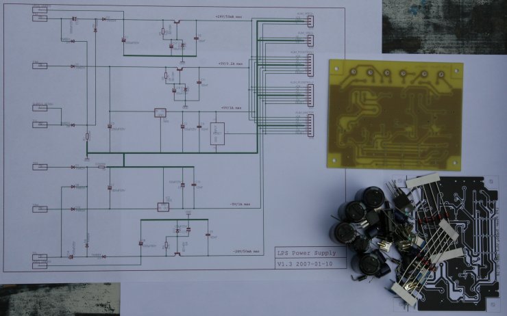
| Board manufactured | |
| Board finished | |
| Board tested | |
Contents |
Description
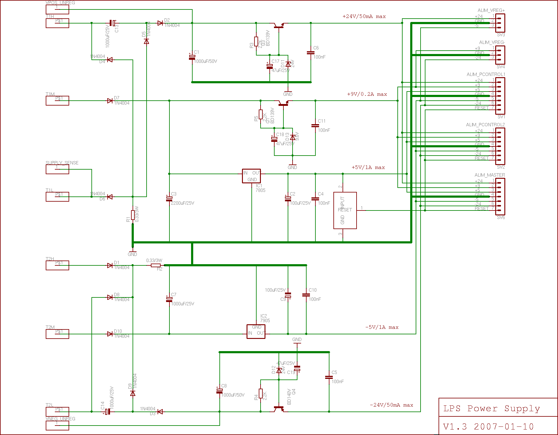
The power supply controllers and the master power supply board need themselves a power supply. To drive the output power supply transistors a specific power supply is used. By doing this it decouples the interactions of the power supply loads on the voltage regulator.
LPS Power Supply
Positive Power Supplies
We have the following needs on the positive supplies:
- Positive Rectifier Board
- The positive rectifier board needs a power supply for the AOP that measure the output currents. These AOP need a +24V and a -5V supply to ensure that the output can vary between 0 and +5V (while the inputs can reach 10/15V).
- Positive Power Supply Controller
- The controller contains an ATMega16 controller, several AOPs and a voltage reference. The AOPs need a +9V and -5V supplies as their outputs need only be in the 0..+5V range. The voltage reference generates a +5.000V from the +9V. The board must also drive the two relays which are in the rectifier board. The relays are driven by +5V and -5V (dV = 10V).
- Positive Voltage Regulator
- The voltage regulator drives the output power transistors using several AOPs. The AOPs must be capable of having an output in the range 0..+20V. For this they need a +24V and a -5V supply.
Negative Power Supplies
We have the following needs on the negative supplies:
- Negative Rectifier Board
- The negative rectifier board is similar to the positive rectifier board but the AOPs need a -24V and a +9V supply. The AOPs outputs are in the 0..+5V range and the inputs may be as low as -10/-15V.
- Negative Power Supply Controller
- This is similar to the positive power supply controller.
- Negative Voltage Regulator
- The voltage regulator drives the output power transistors using several AOPs. The AOP must have the outputs that vary between 0 and -20V and 0 and +5V. They need a -24V and a +9V supply.
Master Controller
- LPS Master Controller
- The master controller contains the ATmega16 controller, drives the LCD panel, a relay and the fans. The relay and fans are connected to the +5V and -5V.
LPS Power Supply Regulation
To obtain the LPS power supplies we use the toric transformer of the positive power supply. The +24V and -24V are obtained by a voltage multiplier from the 2x9V toric transformers. In theory it can reach 36V so the decoupling capacitor is chosen to support at least 50V. The voltage multipliers use 1000uF electrolytic capacitors and the voltage rippling can be approximated to: <math> \Delta V = \left ( \frac{i * \Delta T}{C} \right ) </math> which should be arround 0.4V if we assume that the output current is less than 40mA. On the other hand the maximum rippling being arround 8V, the time is given by the formula <math> \Delta T = \left ( \frac{C * \Delta V}{i} \right ) </math> which gives us arround 200ms during which we will continue to have a stable +24V/-24V.
LPS Power Supply Summary
| +24V | +9V | +5V | -5V | -24V | |
| Positive Power Supply Rectifier | x | x | |||
| Negative Power Supply Rectifier | x | x | x | ||
| Positive Voltage Regulator | X | X | |||
| Negative Voltage Regulator | X | X | |||
| Positive Power Supply Controller | R | X | X | X | |
| Negative Power Supply Controller | X | X | X | R | |
| LPS Master Controller | X | X | |||
| LPS LCD Panel | x | x |
- X
- The supply voltage is used by the board.
- x
- The supply voltage is used but passed throught a specific connector.
- R
- The supply voltage is not used but necessary (it is relayed to another board).
The following tables indicates the maximum current rating for the boards and for each power supply.
| +24 | Positive Power Supply Rectifier | Analog | 10mA | Analog power supply for operational amplifiers. |
| Positive Voltage Regulator | Analog | 20mA | ||
| +9V | Negative Power Supply Rectifier | Analog | 10mA | |
| Negative Voltage Regulator | Analog | 20mA | ||
| Positive Power Supply Controller | Analog | 30mA | ||
| Negative Power Supply Controller | Analog | 30mA | ||
| +5V | Positive Power Supply Controller | Digital | 80mA | |
| Negative Power Supply Controller | Digital | 80mA | ||
| LPS Master Controller | Digital | 250mA | ||
| LPS LCD Panel | Digital | 100mA | ||
| -5V | Positive Power Supply Rectifier | Analog | 50mA | Used by the AOPs and the relays. |
| Positive Power Supply Controller | Analog | 20mA | Used by 2 TL074 | |
| Negative Power Supply Rectifier | Analog | 50mA | Used by the AOPs and the relays. | |
| Negative Power Supply Controller | Analog | 50mA | ||
| -24V | Negative Power Supply Rectifier | Analog | 20mA | |
| Negative Voltage Regulator | Analog | 20mA |
Schematics
PCB
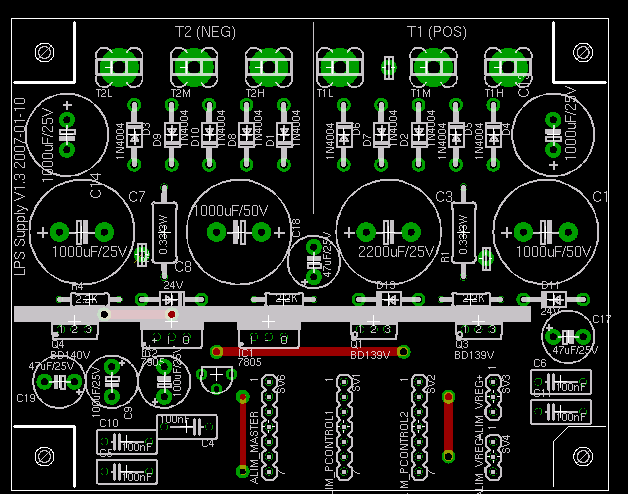
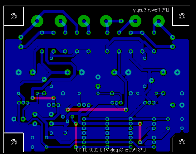
The LPS power supply placement board is 102mm x 80mm wide on a single sided 35um copper board. The placement of VPOS_UNREG and VNEG_UNREG are not the best we could find as they are more or less in the middle of the board. They were added quite late, after all the schema was successfully routed on the single sided board.
| Signal class | Width | Clearance | Drill |
|---|---|---|---|
| Supply | 1.4mm | 0.3mm | 1mm |
| GND | 1.8mm | 0.4mm | 1mm |
| Supply24 | 1mm | 0.3mm | 1mm |
| Signal and others | 0.8mm | 0.3mm | 0.8mm |
Datasheets
Below is a collection of datasheets, white papers and articles related to the parts used in the board.
Resistors
Capacitors
- [SOLID POLYMER ALUMINUM CAPACITOR CHIPS IN DC-DC CONVERTER MODULES REDUCE COST AND SIZE AND IMPROVE HIGH-FREQUENCY PERFORMANCE ]
- [CONDUCTIVE POLYMER ALUMINUM SOLID ELECTROLYTIC CAPACITORS ]
- [Electrolytic Capacitor Guide ]
- [EPCOS Electrolytic Aluminium Capacitor (22000uF/25V) ]
- [EPCOS Electrolytic Aluminium Capacitor (22000uF/16V) ]
Semiconductors
- [L7800 series voltage regulator ]
- [BZX85 Zener Diode ]
- [BD139 NPN Transistor ]
- [BD140 PNP Transistor ]
- [Undervoltage Sensing Circuit ]


